
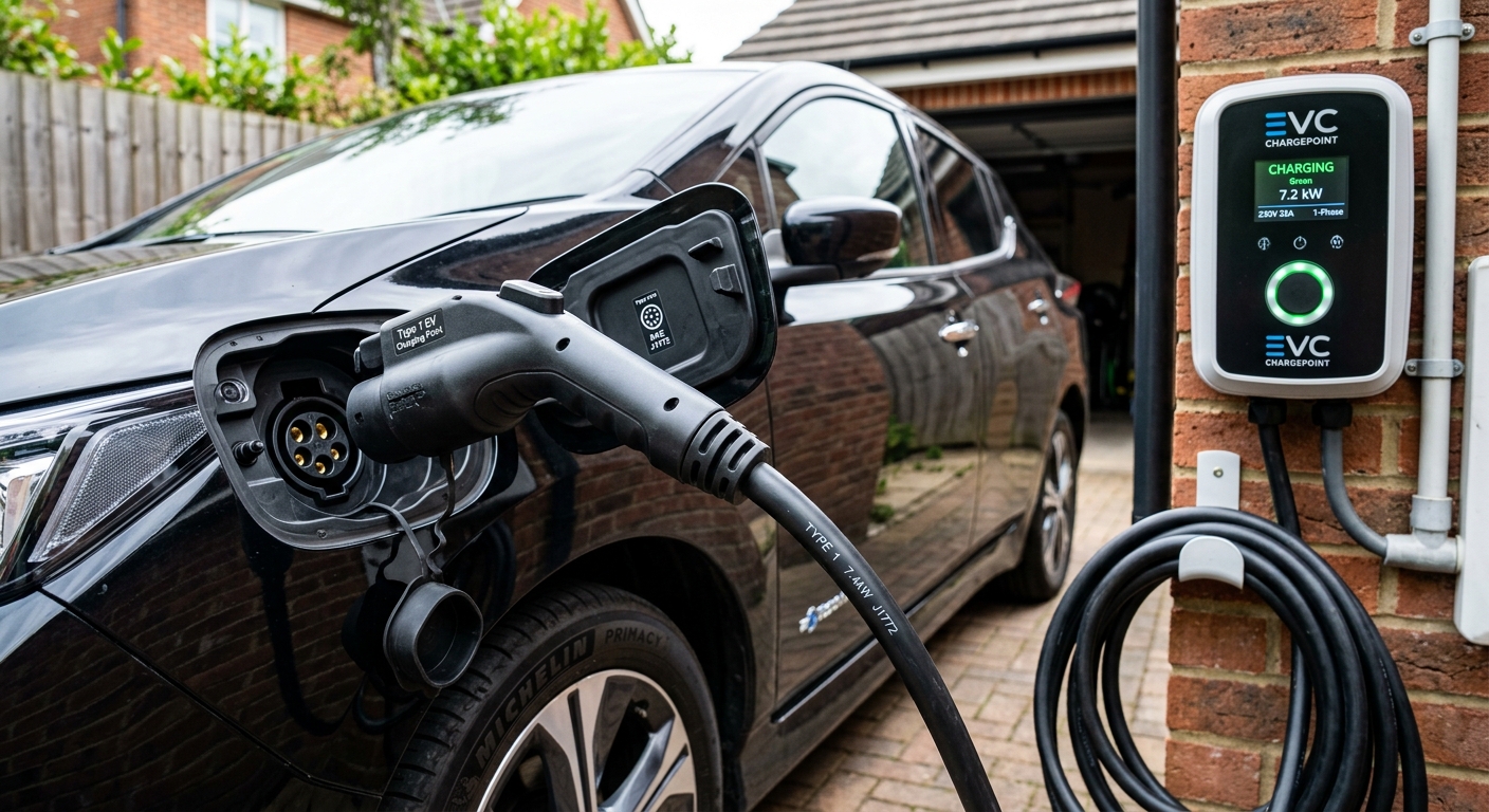
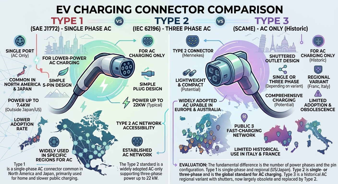
In the landscape of electric vehicle (EV) infrastructure, Type 1 EV charging represents one of the foundational building blocks of residential and commercial AC power delivery. Standardized under SAE J1772 (and designated globally as IEC 62196-2 Type 1), this single-phase Alternating Current (AC) connector served as the universal plug for virtually every non-Tesla electric car sold in North America and Japan for well over a decade.
Whether you are plugging an EV into a standard 120V household wall outlet for Level 1 trickle charging or connecting to a 240V hardwired wallbox for Level 2 charging, Type 1 hardware provides the critical bridge between utility electrical grids and an EV’s internal onboard charger.
In this comprehensive technical guide, we break down how the 5-pin Type 1 plug works, its electrical specifications, mathematical formulas for calculating charge times, safety handshakes, and how Type 1 adapts to modern CCS1 and NACS (SAE J3400) charging standards.
To explore how AC destination chargers interact with intelligent grid software, read our guide on smart charging technology. For a global overview of how Type 1 compares to European and Asian plug types, visit our guide on charging types or head directly to our main portal at EV Charger Advisor.
1. What Is a Type 1 (SAE J1772) Connector?
The Type 1 plug—widely known as the J1772 plug or “J-plug”—was introduced by the Society of Automotive Engineers (SAE) to establish a universal interface for electric drive vehicles.
               Type 1 (J1772) Pin Layout
             ┌─────────────────────────┐
             │       ( L1 )   ( L2/N ) │  <-- AC Power Pins
             │                         │
             │   ( CS/PP )   ( CP )    │  <-- Safety / Signal Pilots
             │                         │
             │         ( PE )          │  <-- Protective Earth (Ground)
             └─────────────────────────┘
Key Mechanical Features
-
5-Pin Circular Design: Features a 43mm diameter round housing containing five conductive pin slots.
-
Single-Phase Architecture: Engineered exclusively for single-phase AC electricity (it cannot natively accept multi-phase AC power found in European 400V grids).
-
Quick-Release Mechanical Latch: Includes a spring-loaded top squeeze-latch. Pressing the latch signals the vehicle controller to break electrical current instantly before the main power contacts disconnect, eliminating dangerous high-voltage electrical arcing.
2. Pin Mapping and Technical Functions
Each of the five pins inside a Type 1 connector fulfills a precise electrical or communication requirement to guarantee safety and prevent electrical shock:
| Pin Designation | Name | Function |
| L1 | AC Line 1 | Transmits primary single-phase AC power from the grid. |
| L2 / N | AC Line 2 / Neutral | Serves as Neutral ($N$) for 120V Level 1, or Line 2 ($L2$) for 208V/240V Level 2 charging. |
| PE | Protective Earth | Ground safety pin. Connects first and disconnects last to shield against electrical shorts. |
| CP | Control Pilot | Transmits a $1\text{ kHz}$ Pulse Width Modulation (PWM) signal between charger and vehicle to negotiate charge rates. |
| PP / CS | Proximity Pilot / Control Switch | Detects plug insertion, prevents vehicle drive-off while plugged in, and signals latch depress to cut power instantly. |
3. Charging Levels Supported by Type 1
The Type 1 connector supports two primary categories of AC conductive charging in home and public environments:
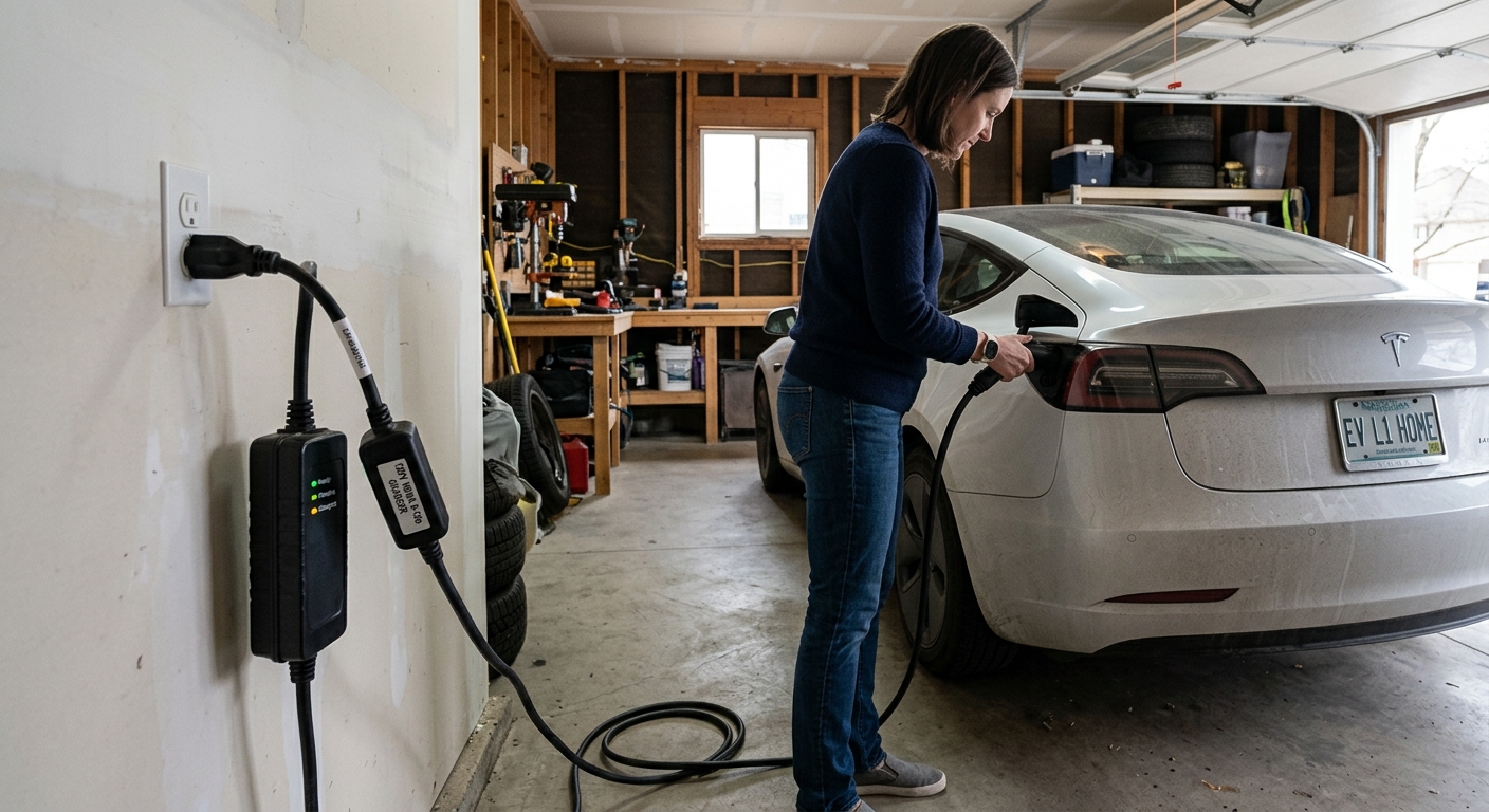
Level 1 AC Charging (120V Standard Household Outlets)
-
Voltage: 120V AC (single-phase standard wall outlet via portable EVSE).
-
Current Range: Typically 12A to 16A continuous draw.
-
Power Output: $1.44\text{ kW}$ to $1.92\text{ kW}$.
-
Charge Rate: Adds roughly 3 to 5 miles of range per hour—ideal for overnight top-ups on plug-in hybrids (PHEVs) or short-commute EVs.
Level 2 AC Charging (208V–240V Dedicated Circuits)
-
Voltage: 208V (commercial 3-phase split) or 240V (residential single-phase).
-
Current Range: 16A up to 80A max continuous load.
-
Power Output: $3.3\text{ kW}$ up to $19.2\text{ kW}$ (most home wallboxes supply 7.6 kW to 11.5 kW at 32A–48A).
-
Charge Rate: Adds roughly 25 to 35 miles of range per hour.
4. Mathematical Deep Dive: Power Delivery & Charge Time Calculation
Calculating energy delivery through a Type 1 J1772 interface relies on standard single-phase electrical power formulas.
Single-Phase AC Power Equation
Where:
-
$P_{\text{kW}}$ = Total AC charging power delivered to the vehicle inlet in kilowatts.
-
$V$ = Operating voltage ($120\text{V}$ for Level 1 or $240\text{V}$ for Level 2).
-
$I$ = Amperage setting configured on the EVSE (Electric Vehicle Supply Equipment).
Time to Charge Formula
Where:
-
$\text{SoC}$ = State of Charge as a decimal (e.g., $80\% = 0.80$, $20\% = 0.20$).
-
$\eta$ = Internal AC-to-DC conversion efficiency of the vehicle’s Onboard Charger (OBC), typically between $0.88$ and $0.92$.
Step-by-Step Applied Calculation
Suppose an EV driver plugs a vehicle with a 75 kWh battery pack (charging from 20% to 80%) into a 240V / 48A hardwired Level 2 Type 1 home charger.
Step 1: Calculate Total Required Energy ($\Delta E$)
Step 2: Determine Delivered Power ($P_{\text{kW}}$)
Step 3: Apply Onboard Charger Conversion Efficiency ($\eta = 0.90$)
Step 4: Calculate Total Duration ($T$)
5. Type 1 and the Evolution to CCS1 & NACS
As electric vehicle battery capacities grew, AC charging speeds (capped at 19.2 kW) were insufficient for long-distance highway travel. This led to two major evolutions based on Type 1 hardware:
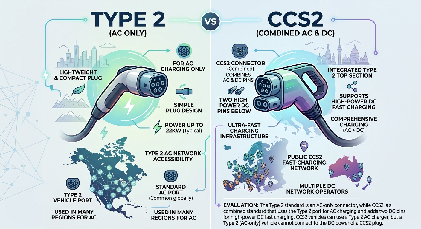
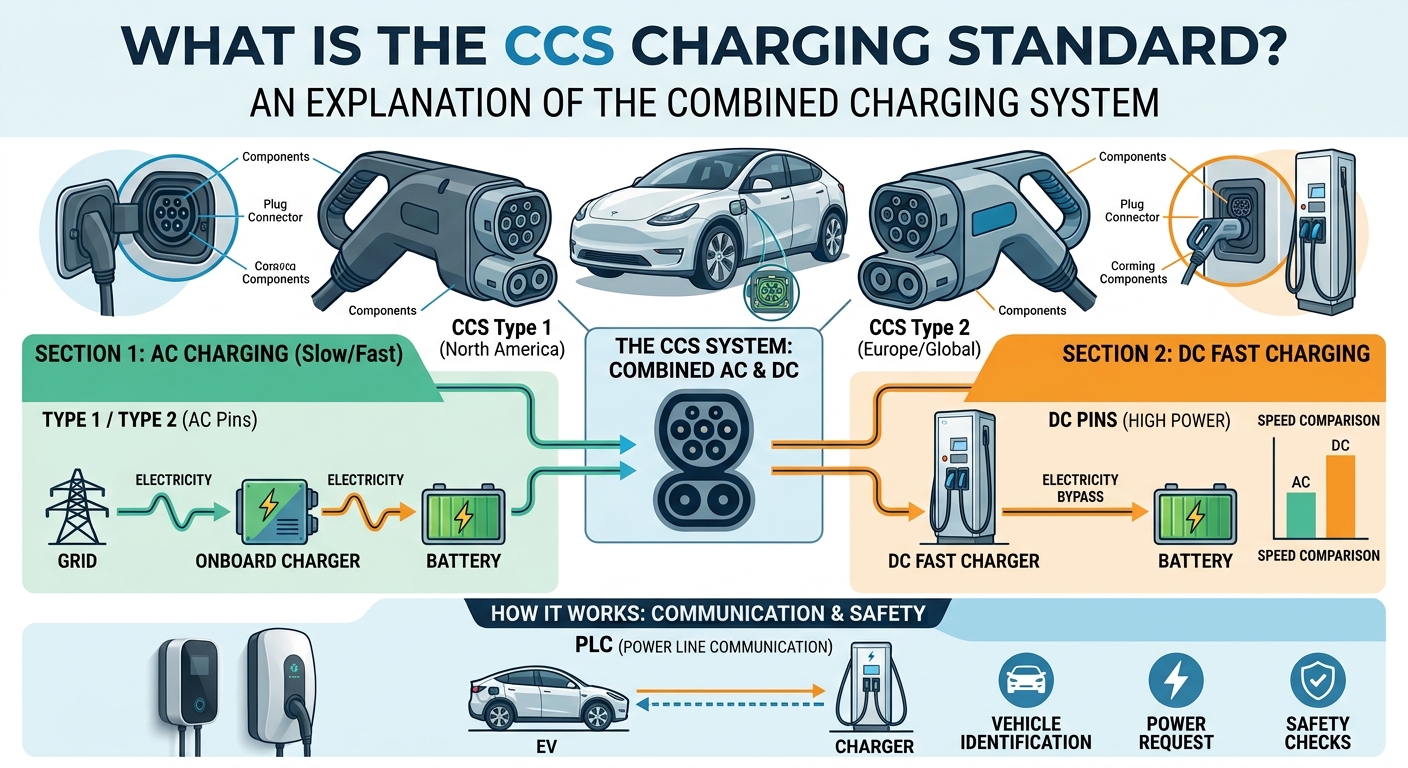
1. Combined Charging System 1 (CCS1)
To add high-power DC fast charging capabilities while maintaining backward compatibility, engineers designed CCS1. CCS1 retains the top half of the standard Type 1 J1772 pin pattern (using the CP, PP, and Ground pins for signaling) and adds two massive direct-current pins underneath. This allowed vehicles to accept up to 350 kW DC at public fast-charging corridors.
2. Transition to NACS (SAE J3400) and Adapters
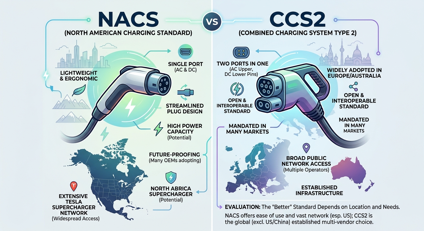
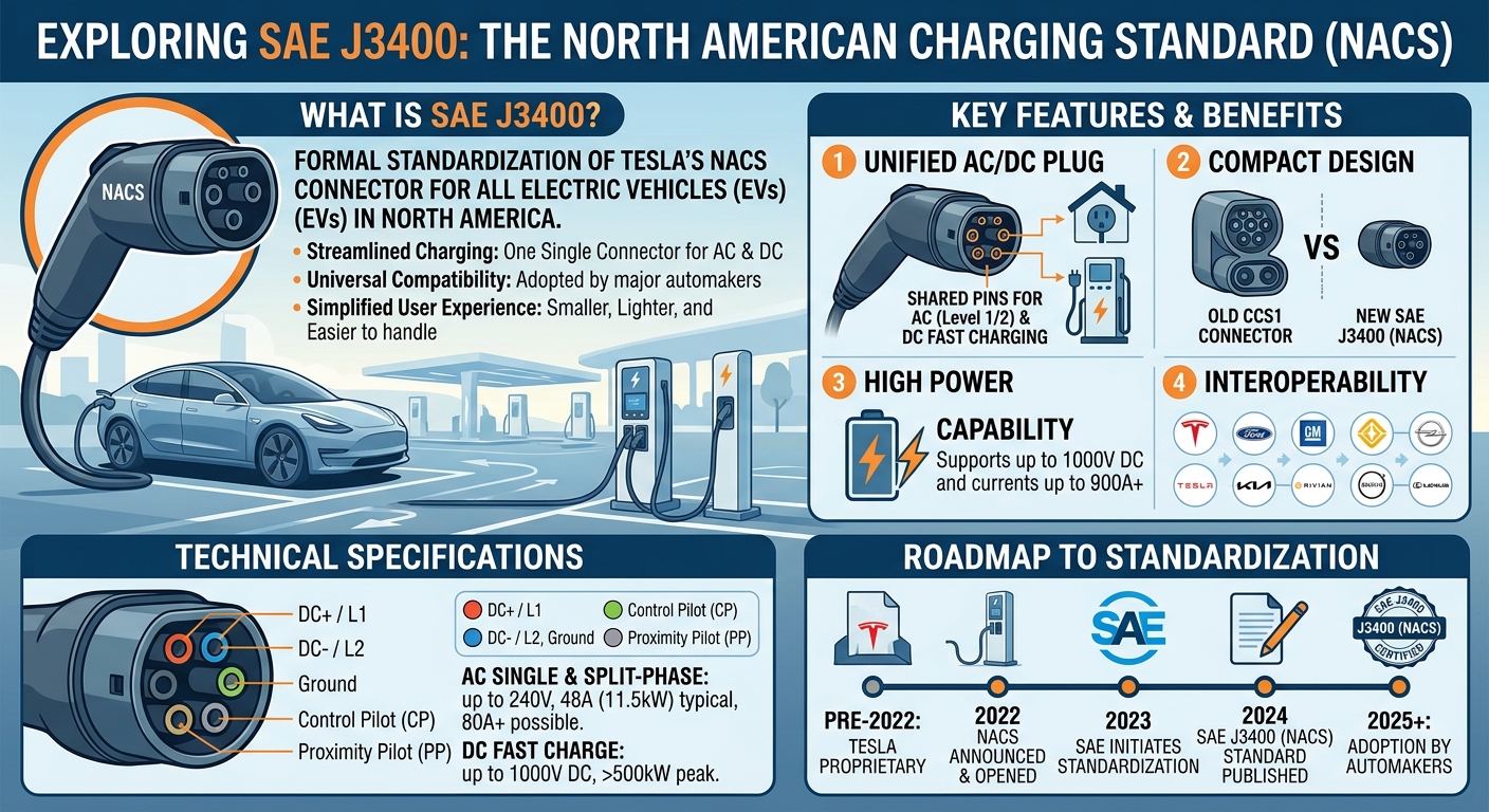
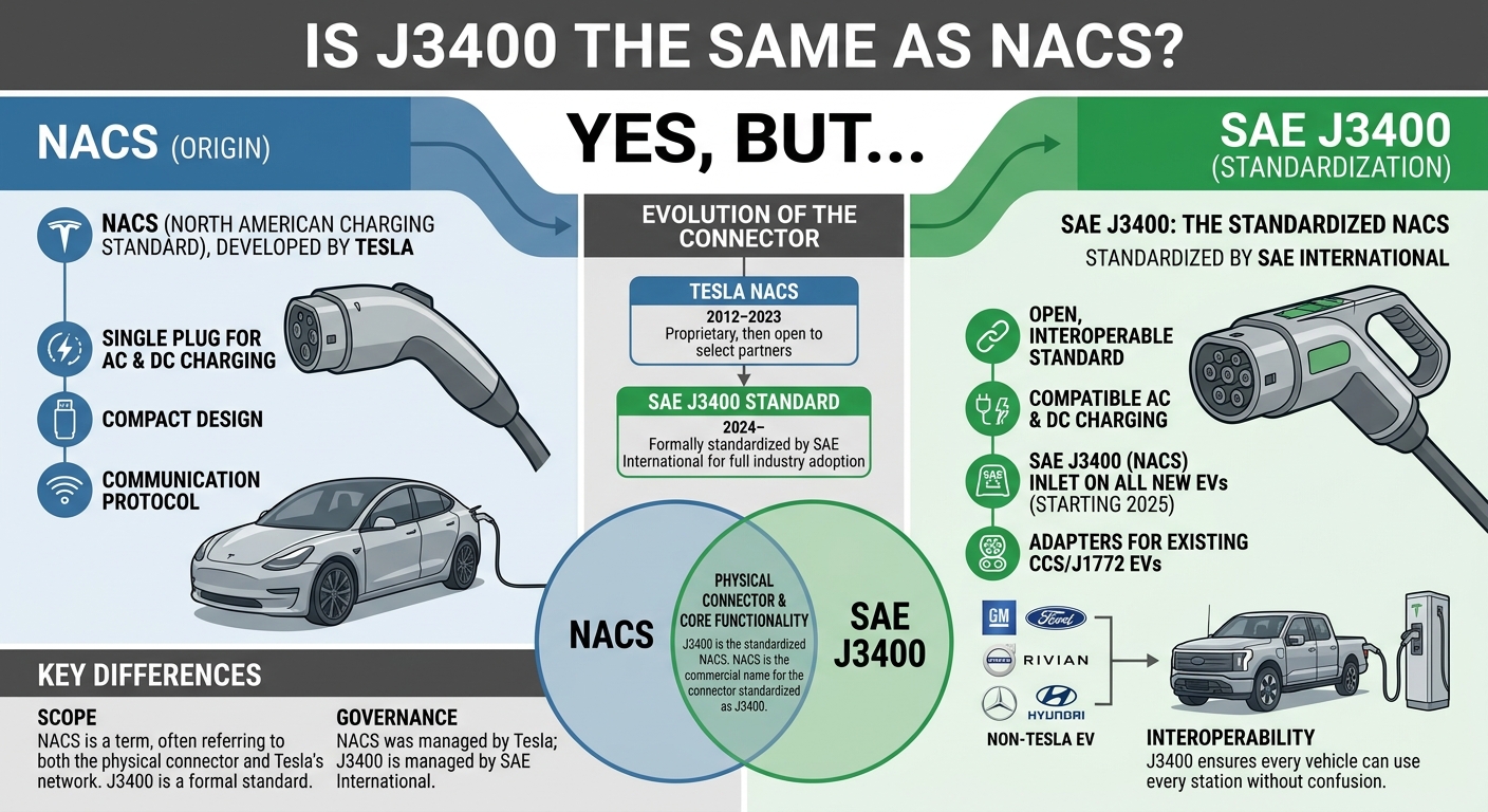
With North America standardizing around the North American Charging System (NACS / SAE J3400), automakers are transitioning native vehicle inlets from Type 1 / CCS1 over to NACS. However, Type 1 remains fully relevant thanks to simple, passive mechanical adapters:
-
J1772-to-NACS Adapters: Allow NACS-equipped vehicles to use millions of existing Level 1 and Level 2 J1772 public and home charging stations.
-
NACS-to-J1772 Adapters: Allow legacy J1772 vehicles to plug into Tesla Destination Chargers and AC wallboxes.
6. Summary
The Type 1 (SAE J1772) connector established the fundamental safety protocols, physical form factors, and pilot signaling rules that define modern electric vehicle charging. While high-speed highway charging has moved to CCS1 and NACS, Type 1 remains a durable workhorse for residential Level 1 and Level 2 AC charging across millions of homes and commercial facilities globally.

Leave a Reply