
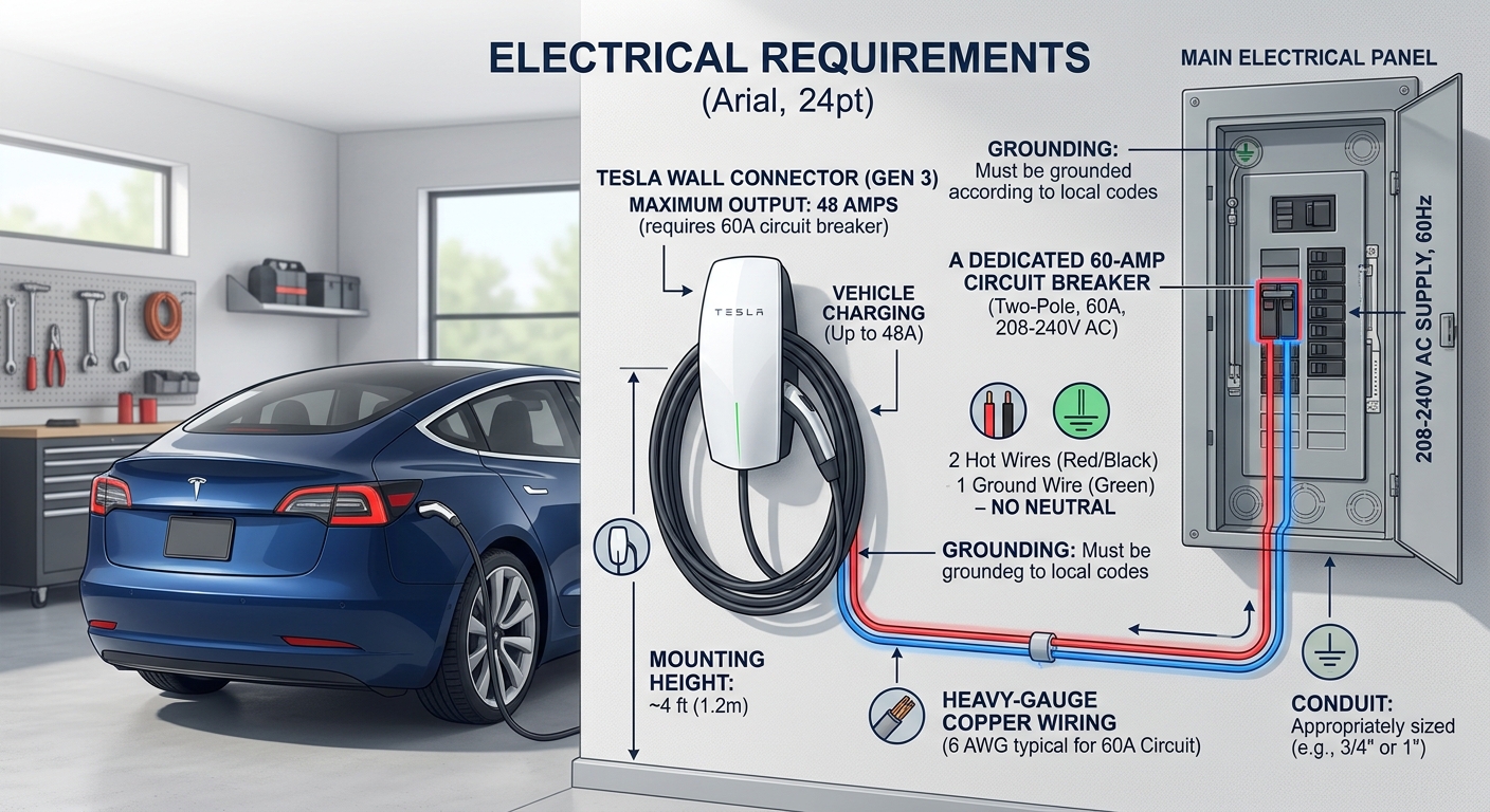
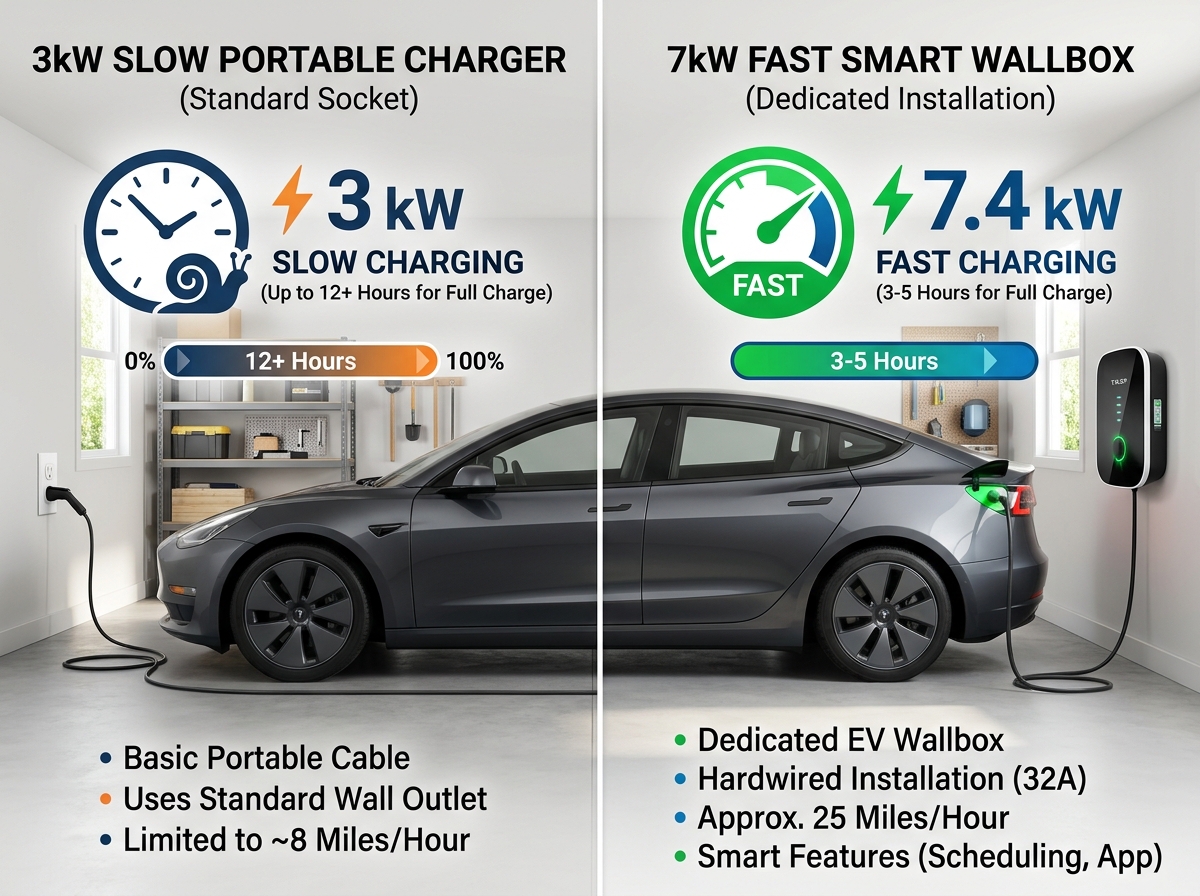
Installing a dedicated home wallbox is the single most effective upgrade for an electric vehicle (EV) owner, providing maximum convenience and lower fuel costs compared to commercial public chargers. Delivering 20 to 44 miles of driving range per hour over a high-voltage single-phase supply, the Tesla Wall Connector (Gen 3 and Universal versions) represents an industry-leading home charging solution. However, before mounting the unit, a crucial question arises: What are the electrical requirements for a Tesla Wall Connector?
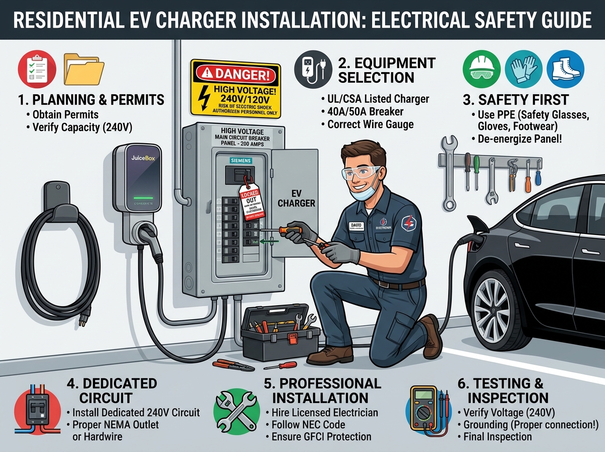
The short answer is: the Tesla Wall Connector requires a dedicated 200–240V AC single-phase branch circuit hardwired with two hot conductors ($L_1, L_2$) and a Ground conductor (no neutral required), paired with a dedicated double-pole circuit breaker sized at 125% of the chosen continuous output current under National Electrical Code (NEC Article 625) standards.
Operating at maximum output (48 Amps / $11.52\text{ kW}$), the Wall Connector requires a dedicated 60-Amp circuit breaker and #6 AWG 90°C copper conductors.
For complete hardware reviews, installer guides, and panel load calculators, visit EV Charger Advisor.
1. Core Electrical Specifications & System Requirements
Meeting Tesla’s official installation specifications ensures safe operation, electrical inspector sign-off, and full manufacturer warranty coverage:
A. Voltage, Phase & Connection Type
-
Supply Voltage: Nominal 200V to 240V AC single-phase (50/60 Hz).
-
Wiring Configuration: 3-Wire Setup consisting of two line conductors ($L_1$ and $L_2$) plus an Equipment Grounding Conductor ($PE$). No Neutral wire is required.
-
Hardwired Only: The Gen 3 and Universal Wall Connectors are hardwired directly into a junction box or rear wiring compartment; cord-and-plug connections (NEMA plugs) are not permitted.
B. Breaker Sizing & The 125% Continuous Duty Rule
Electric vehicle charging is classified by NEC 625 as a continuous load (operating for 3 hours or more continuously). Circuit breakers must be sized to 125% of the desired continuous charging amperage:
-
For 48A Charging Output: Requires a 60A Double-Pole Breaker ($48\text{A} \times 1.25 = 60\text{A}$).
-
For 40A Charging Output: Requires a 50A Double-Pole Breaker ($40\text{A} \times 1.25 = 50\text{A}$).
-
For 32A Charging Output: Requires a 40A Double-Pole Breaker ($32\text{A} \times 1.25 = 40\text{A}$).
C. GFCI & Disconnect Requirements
-
Built-in Ground-Fault Protection: The Tesla Wall Connector features integrated CCID50 ground-fault circuit interruption. Do NOT install a GFCI circuit breaker in the panel, as dual-GFCI setups trigger false nuisance trips.
-
Standard Circuit Breaker: Use a standard, non-GFCI double-pole breaker matching your main panel brand.
To learn more about how charger power levels and wire sizes compare, check out our guide on EV charging types.
2. Conductor Wire Sizing & Commissioning Setup
Selecting proper conductor gauges and executing software commissioning prevents thermal overloading:
-
Copper Conductors Only: Tesla specifies solid or stranded copper conductors only (aluminum wiring is not permitted).
-
Wire Gauge Recommendations:
-
60A Circuit (48A Output): Minimum #6 AWG Copper with 90°C THHN/THWN-2 rating (or #4 AWG if using NM-B / Romex cable restricted to 60°C ampacity).
-
50A Circuit (40A Output): Minimum #8 AWG Copper (or #6 AWG for longer runs).
-
-
Software Amperage Commissioning: After physical mounting, the electrician or installer must connect to the Wall Connector’s internal Wi-Fi network using the Tesla One app to set the internal output amperage to match the installed circuit breaker size.
To explore Wi-Fi-enabled smart wallboxes engineered with integrated load management features, read our guide on smart chargers.
Step-by-Step Mathematical Example: Circuit Sizing & Voltage Drop Math
Let us calculate the required breaker size, continuous power delivery, and percentage voltage drop ($\Delta V$) for a hardwired 48-Amp Tesla Wall Connector ($240\text{V}$ single-phase supply) installed on a 70-foot ($21.33\text{ m}$) run using #6 AWG Copper Wire ($R = 0.000491 \Omega/\text{ft}$).
Given Parameters:
-
Continuous Charging Current ($I$): $48 \text{ Amps}$
-
Nominal Line Voltage ($V$): $240 \text{ Volts}$
-
One-Way Cable Length ($L$): $70 \text{ feet}$
-
Conductor Resistance ($R_{\text{wire}}$): $0.000491 \Omega \text{ per foot}$
Calculation 1: Required Breaker Sizing (NEC 125% Continuous Duty)
Calculation 2: Continuous Power Delivery ($P$)
Calculation 3: Voltage Drop ($\Delta V$) Math
For a single-phase 240V circuit ($2 \times L = 140\text{ ft}$ total conductor path):
Calculation 4: Percentage Voltage Drop (%)
Result Breakdown: A 1.38% voltage drop stays comfortably below the 3% maximum NEC threshold limit, proving that a 70-foot run of #6 AWG copper wire safely delivers full 11.52 kW charging output.
Comparison Table: Tesla Wall Connector Circuit Configuration Options
| Breaker Size | Max Continuous Output | Power Output at 240V | Minimum Copper Wire Gauge | Added Range per Hour |
| 60 Amps | 48 Amps | 11.52 kW | #6 AWG Copper | 36 to 44 miles/hr |
| 50 Amps | 40 Amps | 9.60 kW | #8 AWG Copper | 30 to 37 miles/hr |
| 40 Amps | 32 Amps | 7.68 kW | #8 AWG Copper | 22 to 30 miles/hr |
| 30 Amps | 24 Amps | 5.76 kW | #10 AWG Copper | 15 to 22 miles/hr |
Summary & Key Takeaways
-
Requires 200–240V Single-Phase: Wired with 2 Line conductors ($L_1, L_2$) and Ground; no neutral required.
-
Apply NEC 125% Sizing Rule: Maximum 48A output requires a dedicated 60A double-pole breaker and #6 AWG copper wire.
-
Do Not Use GFCI Breakers: The unit features internal ground-fault protection; install a standard non-GFCI breaker.
-
Commission Amperage in App: Ensure your installer sets the matching breaker limit in the Tesla One app during setup.

Leave a Reply