
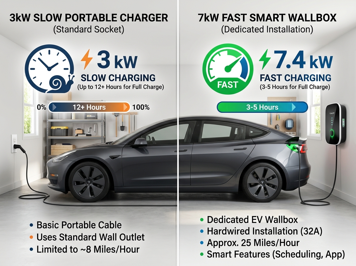
Pairing an electric vehicle (EV) with residential solar photovoltaics (PV) represents the ultimate sustainable energy loop, allowing you to fuel your car directly from sunlight. Delivering 20 to 44 miles of driving range per hour over a high-voltage 240-volt single-phase branch circuit, installing a Level 2 wallbox makes home charging effortless. However, homeowners frequently ask about the underlying hardware architecture: How do you connect an EV charger to solar panels?
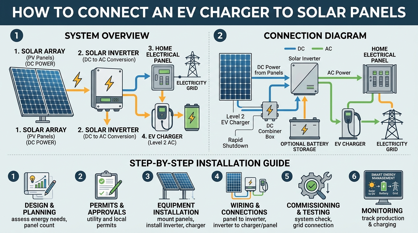
The short answer is: you connect an EV charger to solar panels indirectly through your home’s inverter and electrical panel, rather than wiring the car charger directly to the solar modules.
Understanding how solar-to-EV coupling works—whether through AC-coupling, DC-coupling, or smart energy management systems (EMS) under National Electrical Code (NEC Article 625 / Article 705) standards—ensures you maximize clean energy self-consumption and lower your charging costs.
For complete hardware reviews, installer guides, and panel load calculators, visit EV Charger Advisor.
1. The Solar-to-EV Connection Architecture
Solar panels generate DC (Direct Current) electricity, while your home and EV operate on AC (Alternating Current) or require regulated DC fast-charging power. Connecting them involves three primary components:
SOLAR-TO-EV CHARGING ARCHITECTURE:
[Solar PV Array] ──► [Solar / Hybrid Inverter] ──► [Main Electrical Panel] ◄── [Level 2 EV Charger]
                                                            ▲
                                                            │
                                                [CT Clamps / Smart Meter]
A. The Indirect Connection Path
-
Solar panels connect directly to a solar string inverter or microinverters, which convert DC power into AC power.
-
That AC power feeds directly into your main electrical distribution panel.
-
Your Level 2 EV charger also connects directly to the main electrical panel on a dedicated branch circuit.
-
The Flow: When your solar panels produce excess electricity during the day, that surplus AC power flows through the main panel and directly into your EV charger. If solar production is insufficient, the home seamlessly draws supplemental power from the utility grid or a home battery bank.
B. Smart EV Charging & Solar Tracking (Eco/Eco+ Modes)
-
Current Transformer (CT) Clamps: Installed on your main service lines, smart CT clamps monitor real-time grid import and export.
-
Solar-Match Diversion: Advanced smart chargers (such as the Zappi, Tesla Wall Connector with Solar Charging, or Emporia Vue) can be configured to charge your EV only when excess solar energy is being exported to the grid, ensuring 100% green charging.
To learn more about how charger power levels and wire sizes compare, check out our guide on EV charging types.
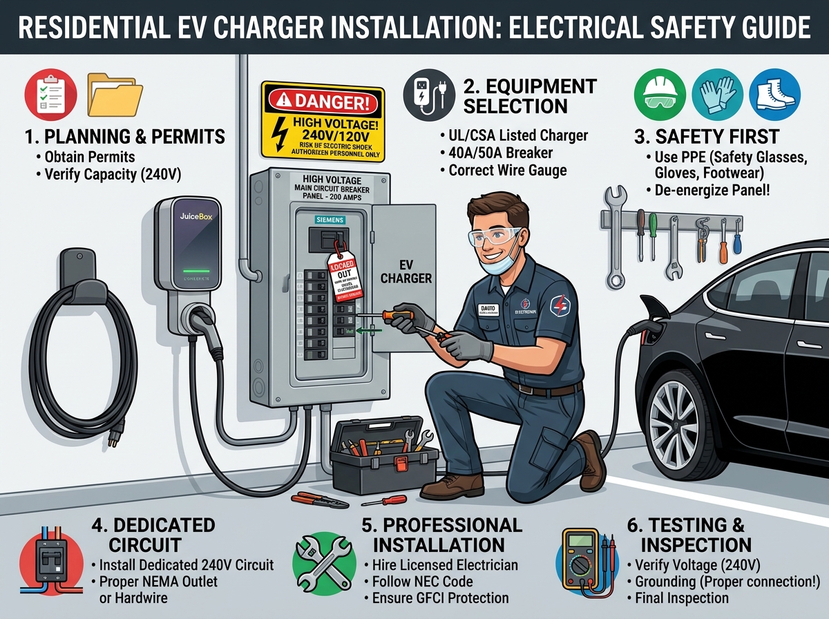
2. Electrical Sizing & Safety Rules (NEC 625 & NEC 705)
Integrating solar production with high-amperage EV charging requires strict adherence to electrical safety codes:
-
NEC 705.12 (The 120% Rule): When feeding power from both solar inverters and the utility grid into a main service panel, the combined breaker ratings cannot exceed 120% of the main panel busbar rating.
-
Dedicated Circuit Sizing (NEC 125% Rule): EV charging is a continuous load. A continuous 48-Amp charger ($11.52\text{ kW}$) requires a dedicated 60-Amp double-pole circuit breaker and #6 AWG copper wire.
-
Hardwired Reliability: Hardwiring your smart EV charger directly to the panel ensures stable CT clamp communication and eliminates thermal degradation.
To explore Wi-Fi-enabled smart wallboxes engineered with integrated load management features, read our guide on smart chargers.
Step-by-Step Mathematical Example: Solar-to-EV Energy Transfer Calculation
Let us perform a technical calculation to determine the daily solar energy generation, self-consumption ratio, and charging duration required to add 35 kWh of solar energy to an EV using a 7.68 kW Level 2 Smart Charger ($32\text{A}$ continuous at $240\text{V}$) connected to a 6.0 kW Solar PV Array operating at 85% system efficiency ($\eta = 0.85$).
Given Parameters:
-
Solar Array Peak Capacity ($P_{\text{solar}}$): $6.0 \text{ kW}$
-
Peak Sun Hours per Day ($H$): $5.0 \text{ Hours}$
-
System Efficiency Factor ($\eta_{\text{sys}}$): $85\% \quad (0.85)$
-
Target Energy to Transfer to EV ($E_{\text{EV}}$): $35 \text{ kWh}$
-
Continuous EV Charger Draw ($P_{\text{EV}}$): $32\text{A} \times 240\text{V} / 1000 = \mathbf{7.68 \text{ kW}}$
Calculation 1: Total Daily Solar Energy Generation ($E_{\text{solar-daily}}$)
Calculation 2: Adjusting for Home Baseline Load & Solar Surplus
Assuming essential daytime home appliances consume 8.50 kWh, the remaining net solar surplus available for EV charging ($E_{\text{surplus}}$) is:
Calculation 3: Charging Duration at 32A Continuous Speed ($T_{\text{solar-charging}}$)
Result Breakdown: A 6.0 kW solar array generates 25.5 kWh daily, providing 17.0 kWh of surplus solar energy that dynamically fuels an EV at a 32A rate for 2 hours and 13 minutes before supplementing with grid power.
Comparison Table: Solar EV Charging Integration Methods
| Integration Strategy | How It Works | Best Suited For | Primary Benefit |
| Standard Grid-Tied Charging | Charges whenever plugged in (draws solar + grid) | All solar homes | Simple setup; ensures car is always charged |
| Solar-Only Diversion Mode | Smart charger ramps up/down to match exact solar export | Sunny climates & low net-metering rates | Maximizes 100% clean solar self-consumption |
| Battery-Buffered Solar Charging | Stores solar in BESS during day; charges EV at night | Time-of-Use (TOU) rate structures | Avoids expensive peak evening utility electricity |
Summary & Key Takeaways
-
Connected via Main Panel: EV chargers connect indirectly to solar panels through your home’s inverter and main electrical distribution panel.
-
Use Smart CT Clamps: Install Current Transformer (CT) clamps to monitor solar export and dynamically route surplus energy into your vehicle.
-
Follow NEC 705 Rules: Ensure panel busbar capacity complies with the 120% rule when combining solar inverter and EV charger breakers.
-
Program Eco Modes: Use smart charger app settings to prioritize 100% solar charging during peak daylight hours.

Leave a Reply