
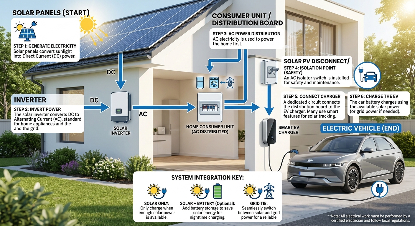
Coupling electric vehicle (EV) charging with residential solar photovoltaics (PV) represents the ultimate sustainable fueling strategy. Operating over a high-voltage 240-volt single-phase branch circuit, installing a solar-compatible Level 2 wallbox delivers 20 to 44 miles of driving range per hour while shifting your vehicle’s energy demand entirely from fossil-fuel utility grids to 100% clean, self-generated solar energy. However, successfully setting up solar EV charging involves more than simply mounting a charger on the garage wall. A primary technical question arises: How do you connect an EV charger to a solar panel system?
The short answer is: connecting an EV charger to a solar panel system requires linking a solar-compatible Level 2 wallbox to your home’s electrical distribution board, installing Current Transformer (CT) clamp sensors on the main utility incoming tails (and PV inverter output), and configuring software modes (Eco / Eco+) via RS-485 data cables or Wi-Fi to dynamically balance solar production with vehicle charging.
Under National Electrical Code (NEC Article 625 / Article 705) standards, proper grid-tied solar integration prevents utility feed-in waste, protects main circuit breaker limits, and maximizes self-consumption savings.
For complete hardware reviews, installer guides, and panel load calculators, visit EV Charger Advisor.
1. Core System Architecture for Solar EV Integration
Integrating solar PV with an EV wallbox relies on three distinct physical and electronic connections:
                  [Solar PV Array]
                         │
                  [Solar Inverter]
                         │
 [Grid Utility] ──► [Main Service Board] ◄── [Solar PV AC Feed]
                         │
                 ┌───────┴────────┐
                 │  CT Sensors    │ (Measures Grid Export/Import)
                 └───────┬────────┘
                         │ (RS-485 Data Cable / Wireless Mesh)
                         ▼
           [Solar-Smart Level 2 Wallbox] ──► [Electric Vehicle]
A. Main AC Electrical Interconnection
-
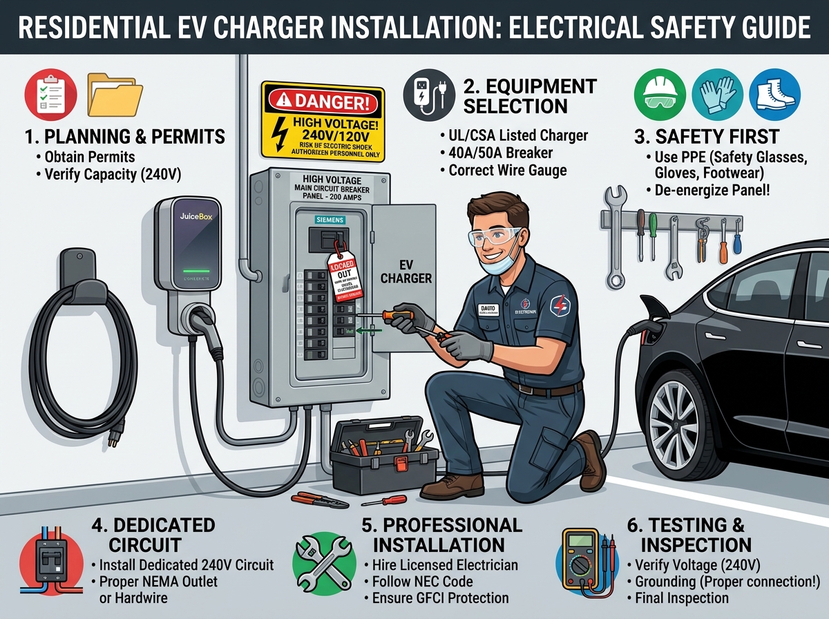
Panel Tie-In: The EV charger is hardwired directly to a dedicated double-pole circuit breaker (e.g., 60A breaker for 48A output) inside the main distribution board. It does not wire directly into the solar panel array or inverter terminals.
-
Shared AC Busbar: Both the solar inverter output and the EV charger branch circuit terminate at the main service panel, allowing solar energy to power the vehicle locally before excess electricity exports to the utility grid.
B. Current Transformer (CT) Clamp Installation
-
Grid CT Clamp: A CT clamp sensor is clipped around the main incoming utility live line ($L_1$). It monitors real-time current direction (grid import vs. solar export).
-
Communication Link: The CT clamp links to the EV charger via an RS-485 signal cable or wireless protocol. When the CT sensor detects solar export to the grid, the wallbox automatically ramps up charging current to absorb the excess energy.
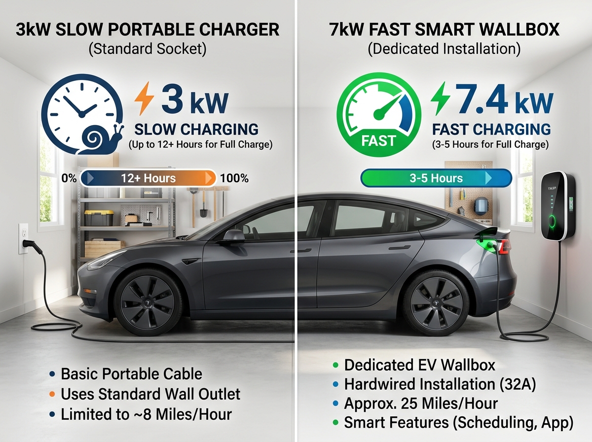
To learn more about how charger power levels and wire sizes compare, check out our guide on EV charging types.
2. Operating Modes: Eco, Eco+, and Fast Charging
Solar-compatible EV wallboxes (such as the Wallbox Pulsar Plus, Zappi, or Enphase IQ EVSE) offer customizable software charging modes:
-
Fast / Full Mode: Charges the vehicle at maximum continuous speed (48A / 11.52 kW), drawing power simultaneously from solar panels and the utility grid as needed.
-
Eco Mode (Solar + Grid Assistance): Prioritizes solar energy absorption. If solar generation drops below the minimum required EV charging threshold (typically 1.4 kW / 6A), the charger pulls a small baseline from the utility grid to maintain continuous charging without stopping.
-
Eco+ Mode (100% Green Solar Only): Pauses charging entirely whenever net solar generation drops below 1.4 kW. Charging automatically resumes as soon as solar panel output recovers, guaranteeing 0% fossil-fuel grid consumption.
To explore Wi-Fi-enabled smart wallboxes engineered with integrated load management features, read our guide on smart chargers.
Step-by-Step Mathematical Example: Solar Surplus Balancing & Charging Math
Let us perform a technical calculation for a home equipped with a 6.0 kW Solar PV Array and a 48-Amp Level 2 Solar Wallbox ($240\text{V}$ AC supply) running in Eco Solar Matching Mode on a sunny afternoon.
Given Parameters:
-
Active Solar PV Generation ($P_{\text{solar}}$): $5.80 \text{ kW (5,800 Watts)}$
-
Active Household Appliance Draw ($P_{\text{house}}$): $1.48 \text{ kW}$ (HVAC + Refrigerator + Lighting)
-
Supply Voltage ($V$): $240 \text{ Volts}$
-
Target Energy Replenishment ($E$): $30 \text{ kWh}$
-
AC/DC Conversion Efficiency ($\eta$): $90\% \quad (0.90)$
Calculation 1: Net Available Excess Solar Power ($P_{\text{surplus}}$)
Calculation 2: Dynamically Adjusted EV Wallbox Amperage ($I_{\text{EV}}$)
To absorb 100% excess solar power without pulling grid energy, the wallbox adjusts continuous current:
Calculation 3: Net Power Delivered to Battery Pack ($P_{\text{net}}$)
Calculation 4: Required Solar Charging Session Time ($T$)
Result Breakdown: The CT sensors dynamically match charger output to 18.0 Amps ($4.32\text{ kW}$), transferring 30 kWh of 100% free solar energy into the vehicle battery in under 7 hours and 45 minutes with zero utility grid draw.
Comparison Table: Solar EV Integration Methods
| Integration Method | Primary Components Required | Solar Matching Capability | Grid Dependency | Installation Complexity |
| Standalone Smart Charger + CT Clamps | Wallbox + Grid CT Clamp Module | Dynamic (Real-Time Solar Tracking) | Zero in 100% Eco+ Mode | Moderate (Standard 240V Circuit + CT Cable) |
| Unified Solar + EV Hybrid Inverter | Solar Inverter with Integrated EV Dock | High (Direct DC/AC Conversion) | Zero during daylight hours | Moderate to High (Requires specific inverter) |
| Basic Charger + Home Battery (BESS) | Wallbox + Solar PV + Storage Battery | High (Charges night or day) | Zero (Powered via BESS) | High (Requires battery storage system) |
| Standard Unmanaged EV Charger | Standard Level 2 Wallbox | None (Fixed full-power draw) | High (Pulls grid power if draw exceeds solar) | Low (Standard 240V Circuit only) |
Summary & Key Takeaways
-
Connect at Main Service Panel: Hardwire the solar EV charger to a dedicated double-pole breaker inside the main electrical panel.
-
Install Grid CT Sensors: Attach current transformer (CT) clamps to incoming utility tails to track real-time solar energy export.
-
Use Solar-Matching Modes: Select Eco or Eco+ software modes to adjust charging rates dynamically, absorbing excess solar power.
-
Follow NEC 625 & 705 Safety Rules: Ensure proper overcurrent protection (125% continuous duty rule) and grid interconnection standards.

Leave a Reply