
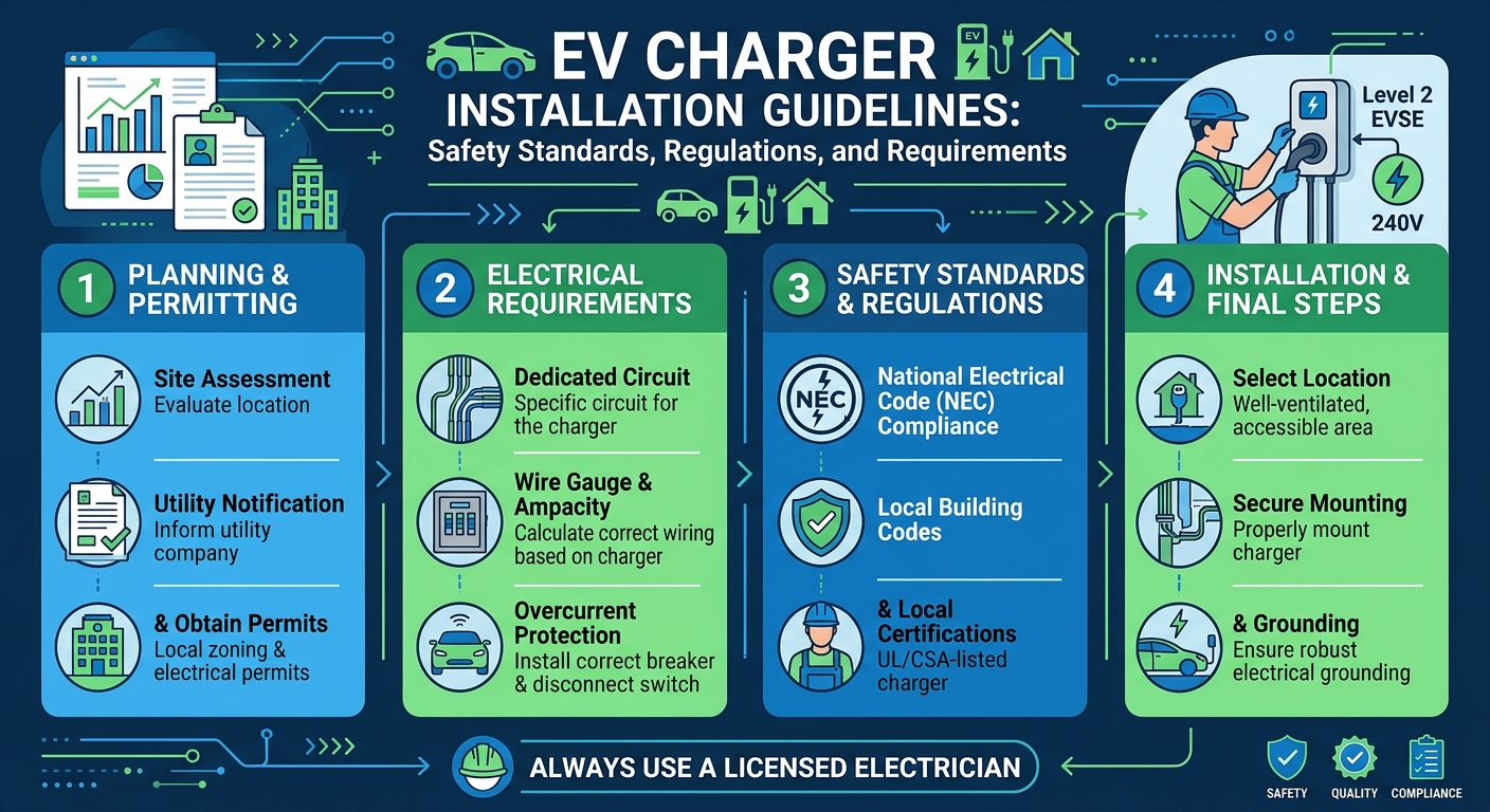
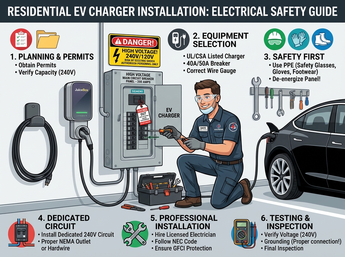
The rapid transition toward electric mobility requires robust, safe, and highly efficient charging infrastructure across residential, commercial, and public sectors. Operating high-voltage alternating current (Level 2 AC, 208–240V / 400V) and direct current fast charging (Level 3 DC, 480V+) systems demands absolute technical precision. Installing electric vehicle supply equipment (EVSE) is not a simple DIY appliance plug-in; it represents a major continuous high-amperage addition to a building’s electrical infrastructure.
Failure to follow standardized safety frameworks can result in thermal conductor degradation, nuisance breaker tripping, severe shock hazards, and non-compliance with local utility regulators.
This comprehensive guide outlines the primary safety standards, National Electrical Code (NEC Article 625) requirements, cable sizing formulas, and international regulatory frameworks (such as Pakistan’s EV Charger Regulations 2026) required for safe, grid-compliant EV charger installations.
For complete hardware reviews, installer guides, and panel load calculators, visit EV Charger Advisor.
1. Regulatory Frameworks: NEC Article 625 & Global Regulations
Electrical engineering governing bodies enforce specific installation rules to manage the sustained thermal stress of EV charging:
A. The National Electrical Code (NEC Article 625)
-
Continuous Duty Classification (NEC 625.42): EV charging is classified as a continuous load (drawing maximum current for 3 hours or more continuously). Overcurrent protection devices (circuit breakers) and conductors must be sized at 125% of the EVSE’s maximum output rating.
-
Dedicated Branch Circuit (NEC 625.40): Level 2 wallboxes exceeding 16 Amps continuous output must be powered by an individual, dedicated branch circuit with no other receptacles or lighting loads.
-
Disconnecting Means (NEC 625.43): For commercial installations or EVSE rated over 60 Amps or 150 Volts to ground, a lockable disconnecting switch must be installed in a readily accessible location within line-of-sight of the charger.
-
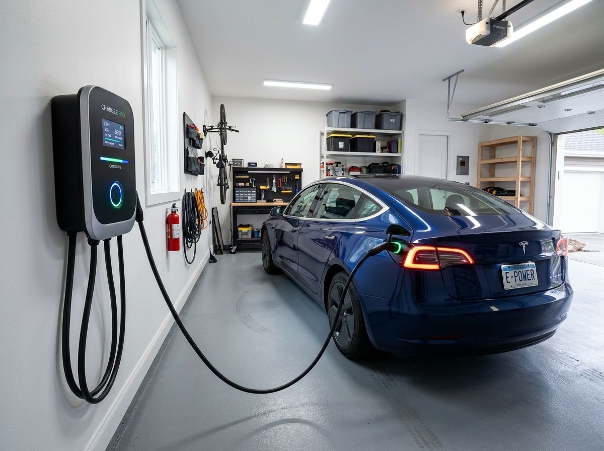
Mounting & Height Limits (NEC 625.50): The coupling handle and wallbox must be mounted between 18 inches (450 mm) above the floor for indoor garages and 24 inches (600 mm) for outdoor installations, extending up to a maximum height of 4 feet (1.2 m).
B. Regional Governance (e.g., Pakistan EV Charger Regulations 2026)
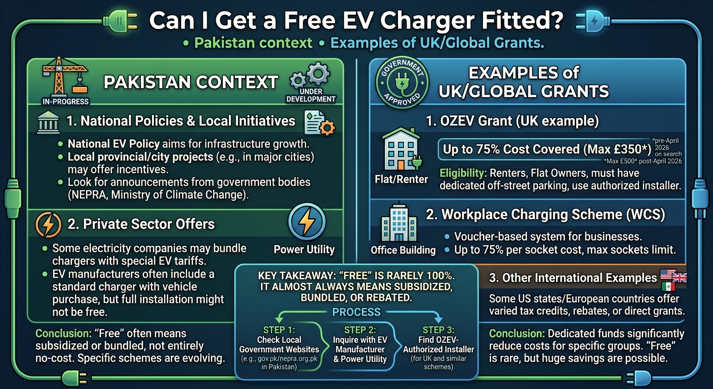
Updated national frameworks like Pakistan’s EV Charger Regulations 2026 (aligned with the National Energy Efficiency & Conservation Authority – NEECA and the New Energy Vehicle Policy 2025–2030) establish clear criteria for commercial and residential grid-tying:
-
Protection Chain Mandate: Requires dedicated Type B Residual Current Circuit Breakers (RCCBs / RCBOs) capable of detecting both AC and DC leakage currents, paired with voltage protection units to withstand grid fluctuations.
-
Discounted Commercial Tariffs: Public EV charging tariffs are regulated (e.g., set at a ~44% discounted rate of ~PKR 39.70/kWh) to encourage private charging hub development.
-
Permitting & DISCO Approvals: Any commercial installation exceeding 25 kW requires technical load inspection from NEPRA / local DISCOs and registration through a streamlined one-window regulatory framework.
To learn more about how charger power levels and wire sizes compare, check out our guide on EV charging types.
2. Electrical Protection Chain & Wiring Standards
A code-compliant EVSE installation requires a multi-layered protection topology from the main distribution board (DB) to the charger outlet:
[Main Supply / Grid Utility]
             │
[Main Service Panel / DB]
             │
 ├── Double-Pole / 4-Pole Circuit Breaker (C-Curve MCB - Sized to 125%)
             │
 ├── Voltage & Phase Protector (Protection against spikes/under-voltage)
             │
 ├── Type B RCCB / RCBO (30mA AC + 6mA DC Leakage Detection)
             │
 ├── Surge Protection Device (SPD Class II / Type 2 for Outdoor Sites)
             │
[Dedicated Heavy Copper Branch Conductor (#6 AWG / 6mm² - 10mm²)]
             │
[Hardwired Wallbox EVSE (Integrated CCID50 Ground Monitoring)]
A. Grounding & Earthing Systems
Proper Earth Bonding is non-negotiable. Standard installations require a dedicated copper conductor (e.g., 10 mm²) connected directly from the charger’s PE terminal to the building main earth bar. In TT earthing networks, neutral-to-earth voltage monitoring or local earth rods must be deployed to prevent open-PEN conductor shock hazards.
B. Mandatory Hardwiring vs. NEMA Receptacles
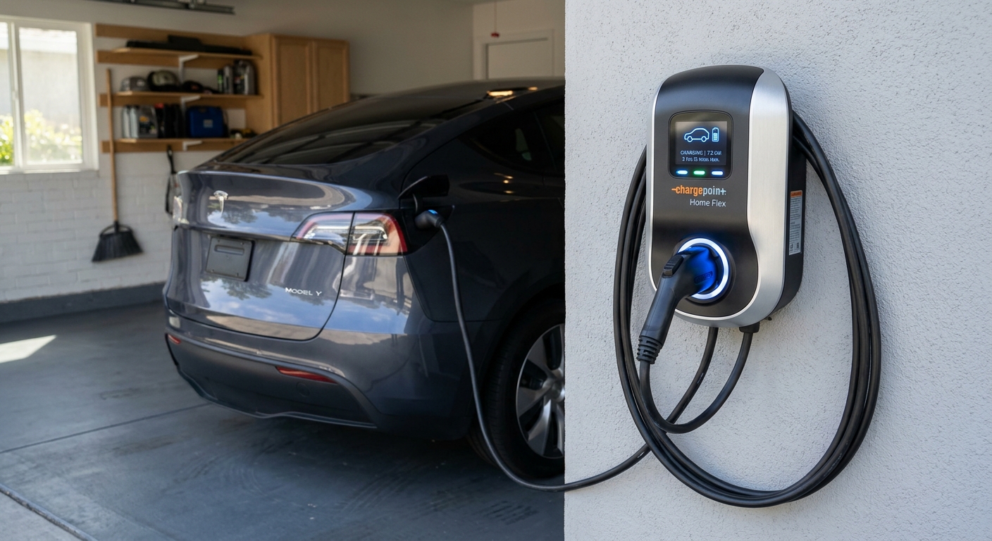
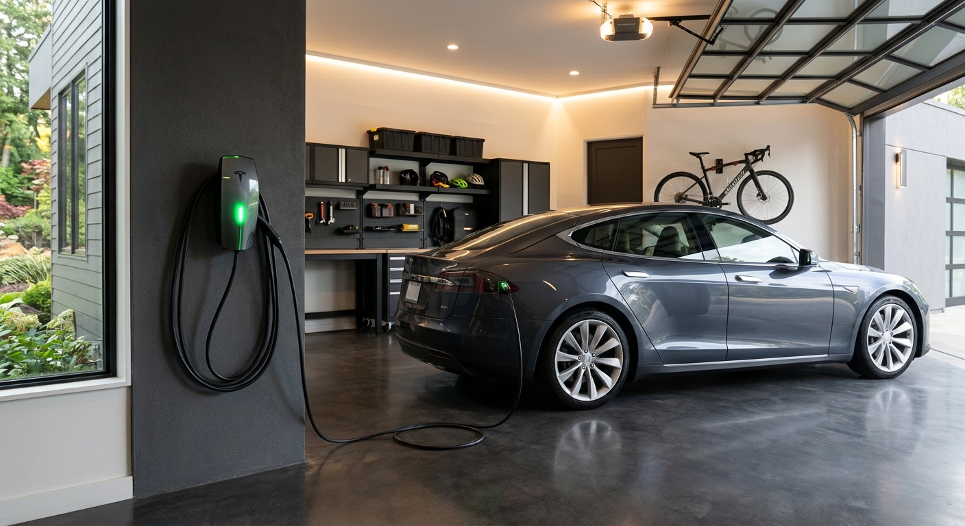
While NEMA 14-50 plug-in setups are common for lower-amperage mobile units, direct hardwiring is the preferred gold standard. Hardwiring eliminates hot-plugging electrical arcing, avoids expensive industrial GFCI receptacle requirements, and allows maximum 48-Amp (11.52 kW) continuous charging on a 60A breaker.
To explore Wi-Fi-enabled smart wallboxes engineered with integrated load management features, read our guide on smart chargers.
Step-by-Step Mathematical Example: Cable Sizing & Voltage Drop Math
Let us calculate the breaker size, continuous charging power output, minimum conductor size, and percentage voltage drop ($\Delta V$) for a single-phase 48-Amp Level 2 EVSE ($240\text{V}$ AC supply) installed on an 85-foot ($25.91\text{ m}$) branch circuit run using #6 AWG Copper Wire (THHN 90°C rating, conductor resistance $R = 0.000491 \Omega/\text{ft}$).
Given Parameters:
-
Continuous EVSE Current ($I$): $48 \text{ Amps}$
-
Nominal Supply Voltage ($V$): $240 \text{ Volts}$
-
One-Way Cable Distance ($L$): $85 \text{ feet}$
-
Conductor Resistance ($R_{\text{wire}}$): $0.000491 \Omega \text{ per foot}$
Calculation 1: Dedicated Circuit Breaker Sizing (NEC 125% Rule)
Calculation 2: Continuous Gross Power Output ($P_{\text{gross}}$)
Calculation 3: Voltage Drop ($\Delta V$) Calculation
For a single-phase 240V circuit ($2 \times L = 170\text{ ft}$ total loop path length):
Calculation 4: Percentage Voltage Drop (%)
Result Breakdown: Sizing the circuit with a 60A double-pole breaker and #6 AWG copper wire safely delivers 11.52 kW continuous charging output while maintaining a 1.67% voltage drop—well within the recommended 3.0% maximum NEC performance threshold limit.
Comparison Table: EV Charger Installation Parameters by Power Level
| Charging Level / Supply | Continuous Current | Recommended Breaker (125%) | Minimum Copper Conductor Size | Protection Chain Standard | Typical Added Range |
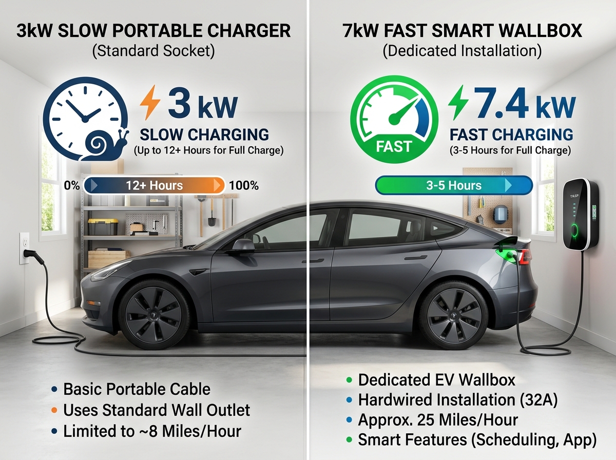
| Level 1 (120V 1-Phase) | 12 Amps | 15A Single-Pole | #14 AWG (2.5 mm²) | Standard 15A GFCI Receptacle | 3 – 5 miles/hr |
| Level 2 Low (240V 1-Phase) | 32 Amps | 40A Double-Pole | #8 AWG / 6 mm² | Type B RCBO + 40A MCB | 22 – 30 miles/hr |
| Level 2 Max (240V 1-Phase) | 48 Amps | 60A Double-Pole | #6 AWG / 10 mm² | Type B RCBO + 60A MCB + SPD | 36 – 44 miles/hr |
| Level 2 Commercial (400V 3-Phase) | 32A per phase | 40A 4-Pole | 6 mm² 4-Core Copper | 4-Pole Type B RCBO + Class II SPD | 60 – 80 miles/hr |
| Level 3 DC Fast (480V 3-Phase) | 80A – 300A+ | 100A – 400A+ | Spec 4/0 AWG to Busbar | Full Industrial Protection / Grid Transformer | 150 – 300+ miles/hr |
Summary & Key Takeaways
-
Apply the NEC 125% Rule: EV chargers are continuous loads; sizing breakers and conductors requires multiplying continuous current draw by 1.25.
-
Dedicated Protection Chain Required: Always install dedicated overcurrent protection, voltage surge protectors, and Type B residual current devices (RCBOs) capable of detecting DC leakage.
-
Hardwiring Superiority: Hardwiring on a 60A breaker provides maximum 48A (11.52 kW) charging while eliminating plug wear, GFCI nuisance trips, and contact heating.
-
Comply with National Regulations: Ensure commercial installations comply with local utility frameworks (such as NEECA and DISCO permits under Pakistan’s 2026 regulations).

Leave a Reply